1.5m REALUMINIZATION PROCEDURE
8/27/97 (from notes of 02/95) -- NC
updated 05/10/18 -- EF
ITEMS NEEDED:
Cart (in warehouse)
Primary Box
Secondary Box
Hoists and buckets (instruction manual)
4 red, 1-inch wide, 44-inch long red "endless" straps (purchased
in 2007). Straps may
have caused spalls, see Removal Procedure.
Randy Lutz (SOML) suggested reaming smooth sections of
the edge. See 07/01/16 email from Gary Rosenbaum.
Shackles, yellow 2-inch slings and carabiniers.
One pallet jack to move the box around (Get one from MMT)
Two Block & Tackles
Crow's foot wrench
Fresh GE IS808 RTV to glue pucks
Removal Procedure
- Remove secondary, put in box. First, disengage carefully the encoder
wire. Use two block and tackles to hold the mirror up while it is
being unscrewed, as the assembly weighs around 50 pounds. The three
innermost bolts, with hex heads are the ones to unscrew. The
earthquake stops must be removed. Place the mirror face up on 4x4
blocks on the roll-around table and unscrew the three allen head
screws from the assembly. Once the screws are out, the mirror may be
wedged away from the assembly (the tripod that is RTV'd to the glass
stays with the glass). Keep track of the Belleville washers (18 per bolt).
- Remove stovepipe, ADC and corrector (go to azel 60 45). First power off
the ADC and the guide camera. Unplug their power cords. Store ADC and corrector
in the clean room, covered with kimwipes.
- Remove counterweight on top ring, replace with restraining rod clamp.
Do this by pointing the telescope to the South, just over the mezzanine.
- Install restraining rods (kept on upper level). First do Dec rod,
the shorter one, with telescope as close to horizon as possible, bump Dec
motion until ball at end of rod seats in the clamp. (Use 1.25 inch
wrench.) The other end is bolted to a square shaped bracket on the
polar axle near the north pier. Use a large open end wrench and a
large screw driver which holds the nut in place to tighten bolt.
Bring scope to zenith and install RA rod, one end goes on main
counterweight arm, the other on the eyeloop on the north pier,
about 4 feet off the floor. This rod should be expanded as much as
possible, because when the telescope is unbalanced in RA, the
tendency will be to compress the rod.
- Loosen worms on both axes, watch for telescope motion.
- Remove all mirror covers so that the struts will clear the covers
when the cell is lowered. Mark or confirm marks on the covers, as
they are unique (make sure the numbers on the doors are
legible). Hinge boxes will not clear the struts, so do it now!
- Remove instrument and back plates with electronics from cell.
- Remove rotator chain and electronics. Watch out when you set down the
assembly, as it is fragile. Remember, the chain has 2 joiners, Wayne.
- Lash finder scope to the telescope with a rope going over a
strut. Remove mounting bolts and flange.
- Remove radial counterweights and the rods by removing the bolt
that holds them in the actuator joints. A two-person job, one on
a ladder removing the bolt, the other holding the counterweight
from below. Good exercise.
- Remove 3 dial indicators from underneath the cell.
- Undo Lou Boyd's spring restraints
underneath the cell.
- Raise cork pads until they just touch the mirror.
- Hook up chain hoists and cart. A shackle is needed on the east
corner of the cart, to make the chain reach the cart. Didn't seem
to matter...
- Raise cart to the cell, make tight.
- Unbolt cell, sets of tape shims to OSS in place so we don't lose them
and we know where each set goes.
- Lower cart to about 3 feet off the floor.
- Remove 3 radial hard points. The hard point on the N side is special,
see Marion Rice's description (PDF).
This is a nice drawing but it DOES NOT provide a torque setting unfortunately.
Unscrew the hex socket (should be finger tight), then the lock nut.
- Remove radial actuators. There is a special wrench for this task,
the (in)famous custom-made crow-foot. Weights must have been
removed first, see above.
- Remove the screw that pins each rotation restraint. This is done
from above the mirror, using a ball driver, and a haemostat to
pull the bolt up.
- Remove earthquake stops.
- Lower the cart to the floor.
- Remove the central plate where the mirror covers rest
when closed. The positioning ball is at the SSE of the plate.
- Place 2 wooden covers (in the mirror box) on top, to work
above the mirror.
- Remove chain hoists.
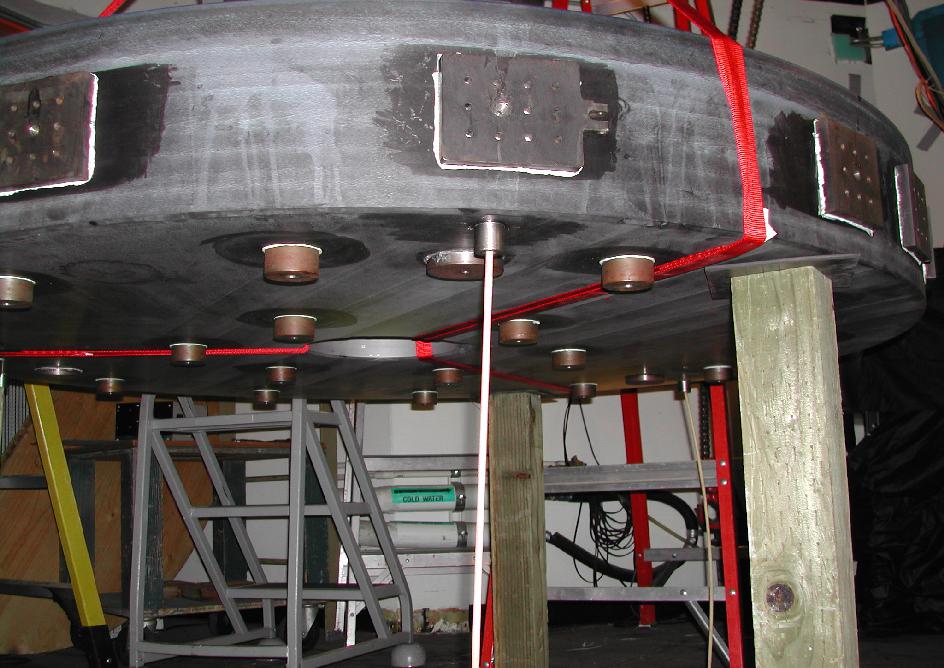
- Place one long yellow strap around SE upper truss, and another at
NW truss, connect with third yellow strap, and attach one of the
hoists at the juncture, which is now in the optical axis. Pics of
the setup are shown below.
- Use 3 red straps looped together over the hoist hook
to remove the mirror. Each strap should be snaked under the
mirror (clocked at 120 degree intervals). Strings are left under
the mirror to pull the straps. The mirror should be raised on its
jacking points to help position the straps. The straps should all
be attached at the center to the hoist hook.
- We have additional red straps, as it turns out. Try adding a 4th strap
for lifting. Actually, 2 of the straps DISAPPEARED somehow. So we're back
to 3 straps.
- Lift mirror from cell.
The estimated mirror mass
(calculation) using its
dimensions and assuming the density of the Duran 50 (Schott) glass
is 2.23 g/cm^3 is 788 kg, or about 1733 lb.
- Remove radial actuators. There is a special wrench for this task,
the (in)famous custom-made crow-foot. Weights were removed before
this step, right?
- Remove the screw that pins each rotation restraint, if the
restraints are mounted. This is done from above the mirror, using
a ball driver, and a haemostat to pull the bolt up. The restraints
were not mounted between 2007 and 2011, but they are in
starting in 2011.
- All 3 axial hard-point pucks are likely to have come unglued at
this stage. There are now scribed marks to re-glue at the right
spots when the mirror is back. Per Gary Rosenbaum, marker ink outgases
too much, so do not use a marker. New plan: do not to glue the hard points.
- Remove cart and cell.
- Move box underneath the mirror. Leave the straps in the box.
- Seal box and ship with secondary and lifting ring, in the flatbed
truck.
Reinstallation Procedure
- Use red straps to lift mirror out of the box, about 4ft above the
floor to clear the top of the cell. Make sure straps are at 120 degree
intervals before lifting the mirror from the box. These straps may have
caused a fracture at the edge of the central hole in Aug 2014. Piece
removed and surface ground out by Randy Lutz of SOML on 8/25/14. Look
into wider straps!
- RTV strings to center tube, to pull straps. There are marks
left after the removal.
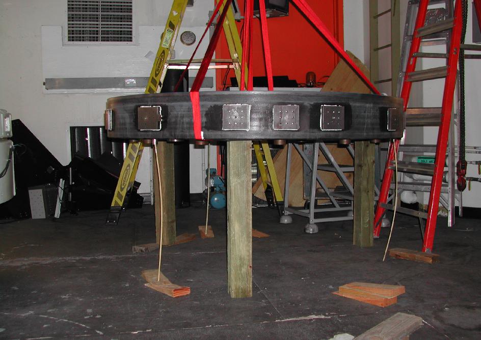
- OLD:If axial hard-point pucks came unglued, glue them on
now. We use RTV, most recently GE
IS808). Make sure to use RTV that has not expired (buy new in
advance if necessary)! Clean off old RTV from the pucks and the
back of the mirror. Use acetone to complete clean-off. Scribe
marks indicate the positions. Pictures
shown here
and here
(08/19/2011) show the pucks glued in place and held up by 3 dowels
with the mirror strung up with the red straps and held stable with
3x27.5-in 4x4 pieces of lumber.
NEW: Do not glue the pucks, leave them floating.
- Use straps to lower the mirror into the cell.
- Raise jack points so that the mirror sits on them instead of
the axial hard points.
- Install push rods for axial actuators while still on the floor.
- Axial hard point pucks should rest on their rods so mirror
will lie on them.
- Make sure radial hard points are retracted.
- Mirror must be aligned to preserve orientation, so the rotational
restraints can be hooked up. There are marks on the cell and the mirror
for alignment that say "align mirror cell." A big N
and "2014" are now scribed on the mirror.
- Engage axial actuators while mirror
is on jacking points. When this is done, lower jacking points.
Leave jacking points barely touching the mirror.
- Set centering after mirror is fully in and axial actuators are
engaged. Use gap gauge to do this with respect to center hub. Use wooden
wedges at the edge of the mirror, on the side pucks. Or use bolts at the
location of the radial hard points to push on the mirror.
- Engage radial hard points once the mirror is centered. Make sure they
are touching, and tighten special hard point (WAP used a torque wrench
that is not great, but set to between 15 and 25 lb-ft).
- Raise axial hard
points until they touch. Lower the jack points a bit, watching the
mirror height relative to the top of the cell (should be about 26
mm). After lowering the jack points, if the
mirror moves down, raise the axial hard points some, to maintain
the height of the mirror in the cell, and distribute the load
between hard and jack points.
- Install center ring for mirror covers.
Also see the view of the ring from the
East side of
the mirror. Note the alignment marks.
- Raise the cell so holes for radial actuators are about eye level
for ease of work on them. Or go all the way up and work on ladders.
- Replacing radial actuators is a pain. It may help to remove at
least one bolt on the bracket attached to the cell to help screw
in the ball-joint pins. Weights should be removed from the rods
during removal, hang them once the arms are mounted. The
counterweights should all hang close to vertically, all at about
the same distance from the side of the cell.
- Finish raising the cell to the struts. Occasionally we have to
bend the struts to get them to mate to the cell bolt holes. A 3-ft
2x4 or crow bar may be useful to bend the W struts into
submission. Raise the cell to within 0.25 inch of the struts.
Tighten all bolts, starting with the W bolts. Once all bolts are
tight, lower cart to the floor.
- The Lou Boyd spring retention system
is tricky. The spring/bolt assembly must be totally taken apart
to reinstall. First, screw bolt into the puck attached to the
mirror, the short thread side goes in - a nut is threaded here to
stop the bolt. Then place the bracket next to the cell (note that
one bracket is bigger than the others as the holes have
different sizes). A large washer comes next, followed by the
spring, followed by a small washer, followed by the nut. The idea
is for each spring unit to have 40 lb of force. The purpose
is to pull the primary down onto the hard points, the
mirror having been floated by the axial counterweights. The hard
points themselves are spring loaded, so too much force is also a
bad idea. The canonical 40 lb is not easy to measure. We decided
to compress the springs equally, to a length of about 2
inches. That compresses the springs some, not too much.
- Fully engage the axial counterweights, distributing the load
as much as possible. They should all hang equally, not touching
either the stirrups or the bottom of the cell. See Lou Boyd's
memo.
- Install 3 dial indicators underneath the cell.
- Lower jack points all the way out at this time.
- Engage the radial counterweights, distributing the load as you go
around the cell.
- Tighten the 3 radial hard points, by hand, as tight as possible.
Tighten the main screw and then the nut against the cell. The N
side hard point is special (see removal instructions above). The N
hard point may need to be tightened to prevent mirror motion. We
gave it 1 1/4 turns on the back screw in Aug 2009, and that helped
quite a bit (no change in dial indicators), especially when
pointed far N.
- The separation between the back of the mirror and the back of the
cell should be about 1.4 inches (0.1 inch tolerance max). Measure with
electronic calipers at the holes where the axial actuator rods engage
in their pucks.
- Continue reattachment in reverse order of removal: earthquake
stops with their tops flush on the edge of the cell, finder scope, rotator,
counterweights, electronics, covers.
- When ready to move the telescope, re-engage worms, remove lock bars,
install mirror covers, stovepipe. For the latter, notice the ball
no longer goes in the hole, it goes where part of the flange was sawed off.
- Re-install the rotator chain. The removable link is inserted from
below. You may want to use a tie-wrap to bring the two ends close
to each other. Make sure the chain is very tight and that the
alignment mark on the W side is aligned with the center of the
large bolt hole (can't miss it).
ALUMINIZATION HISTORY:
Aluminization August 2016.
Aluminization August 2014.
Aluminization August 2011.
Aluminization August 2009.
Aluminization record (PDF)
1983-1995.