The 4shooter camera was developed by Andy Szentgyorgyi and John Geary at the CfA. It employs 4 edge-buttable, thinned and AR coated Loral CCD's. The chips have a 2048x2048 format with 15-micron pixels. At the focal plane, these map into un unbinned pixel scale of 0.337 arcsec (updated for the historical record, from 0.333 on 11/10/04; thanks to Daves Monet and Latham).
Some of the information below is also contained in the 4shooter operating manual
Login as 4obs. To startup the realtime system, type "go4". "split" and "nosplit" will change the readout format. We recommend using "nosplit" for the time being (and so it is the default upon startup). "ccd program serial parallel" will give you full resolution, unbinned. "ccd program off" gives 2x2 binning.
Data are stored in /4sh/flwo2/2002/etc. The format is fits-extensions, so ccd filetype must always be set to EXTFITS (i.e., ccd filetype extfits). Some old scripts may try to set the filetype to be iraf or fits - these will not work. The data files are of course large (8 Mby for 2x2 binning), consequently the disk partitions will fill up faster than you are probably used to. The /4sh directory is large enough for 3-4 nights worth of data, so you'll need to clean out the directories for longer runs. Please clean out all of your directories at the end of your run.
You may want to center the telescope at the center of the array (for mapping), or you may want the center to be on one of the individual chips (for small objects). Check the startup instructions on how to do both.
IRAF : Use cl as usual to start up Iraf 2.11. To bring up saoimage, type simtool, and give flwo48:0 as the display, or use ximtool.
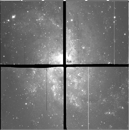
Use mscdisplay to display images (ex. mscdispl 0004.M31 1); mscexamine to examine them (like imexamine). Make sure you have set stdimage=imt1024. Other mosaic commands can be found in the package "mscred" (loaded at startup). Warning. A "feature" of the mscred package is that coords are always in detector units, in this case one unbinned pixel. So, if you take binned data, and use mscdisplay or mscexamine, the pixel values shown in your imtool (saoimage, ximtool etc) and in your fwhm as gotten from radial profile fits will seem to be twice as big as they should be.
To use familiar iraf commands like imhead and imstat, you must specify the frame as well as the image section: e.g. imstat 0001.FLAT[2][100:200,100:200], or display 0004.M31[1] 1. Also, check out the mscred command msccmd, which lets you apply commands such as imhead or imstat to all the sections of an image.
Suggested flat field exposure times are
B 25s
V 14s
R 8s
I 6s
Do not take U or u dome flats - they will not work. Use either twilight or dark sky flats. There is a useful script that we recommend you try for U or u band flats.
Because of the large field of 4shooter, a noticeable vignetting will be seen in exposures less than about 6 seconds, due to the opening and closing time of the shutter. We suggest that all exposures, especially flats and standards be longer than this time.
From a night in Dec 1998, the following transformation from 24 standard stars in V was obtained (using chip 3).
Vstd= -2.5 log10(counts/exptime) + 23.092 - 0.15X - 0.06(B-V)Here are count rates for a V=20 mag zero color star at 1 airmass (from standard stars taken on Nov 11, 1999), using the Harris filter set (all below is for chip 1):
U   2.0 adu/sec  (1 adu = 3.8 e-)
B  11.5
V  12.0
R  13.7
I   6
Here are dark sky rates, likewise for Nov 11, 1999.
U   0.26 adu/s
B   0.77
V   2.3
R   5.0
I   7.6
B sky brightness is about 22 mag per sq. arcsec; V is about 21.0.
Readout noise is about 9 e- for each chip. Gains are 3.8, 3.8, 3.8 and 3.4 for chips 1,2,3, and 4 respectively.
Here are the relative efficiencies between chips, in the R band:
Chip  Chip N/Chip 1
1        1
2        0.91
3        1.10
4        0.85
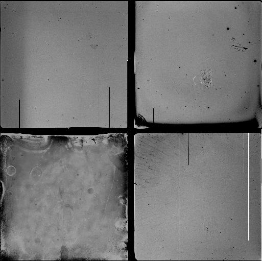
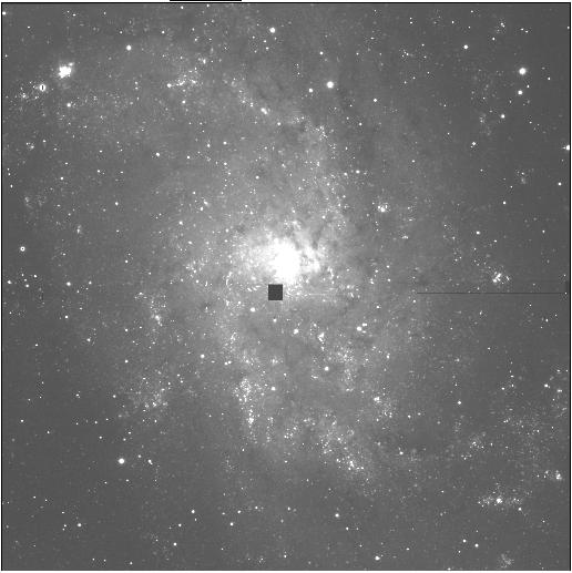
Here is an example of a B Flat.
Here is an example of an R Flat.
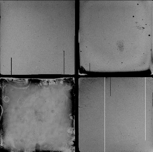
Here is an example of a Bias.
Here are bad pixel maps for unbinned mode, before trimming. Save these to disk (shift left mouse button), hedit the bpm keyword in each channel for each image to match these file names (e.g. hedit filname.fits[1] bpm bpm.IM1.pl etc.)
Here are bad pixel maps for 2x2 binned mode
#   4 - S H O O T E R
#
# CHIP GEOMETRY
#
#   North is UP, East to the LEFT
#
#      non-split mode                   split mode
#
#    A       B  A      B            A       B  A       B
#    +-------+  +------+            +-------+  +-------+
#    |       |  |      |            |   |   |  |   |   |
#    |   3   |  |  4   |            | 3 | 7 |  | 4 | 8 |
#    |       |  |      |            |   |   |  |   |   |
#    +-------+  +------+   West     +-------+  +-------+    West
#    +-------+  +------+            +-------+  +-------+
#    |       |  |      |            |   |   |  |   |   |
#    |   2   |  |  1   |            | 6 | 2 |  | 5 | 1 |
#    |       |  |      |            |   |   |  |   |   |
#    +-------+  +------+            +-------+  +-------+
#    B       A  B      A            B       A  B       A
#
#
Chip 2 is worse than the others, cosmetically and in quantum efficiency.
Gap measurements (in binned [30 micron] pixels):
Chip 1 is 49 pix separated from edge of 2 in X (EW), 6 pix in Y (NS)
     3    12                            2            27
     4    37                            2            40
So, the inter-chip gaps are about 30 arcseconds.
Rotations:    chip 1 rotates into 2 by 0.3495 degrees (3 pix about center)
                   3              2    0.1765
                   4              2    0.021